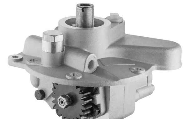
The hydraulic gear pump is the heart of the hydraulic system, referred to as the oil pump. In a hydraulic system, there must be at least one pump. Hydraulic gear pump is an energy conversion device, its function is to make the flow move and convert mechanical energy into fluid energy. The pump is the power element in the hydraulic transmission system. It is driven by the prime mover, takes out the mechanical energy from the output power of the prime mover, and converts it into the pressure energy of the fluid to provide pressure oil for the system. Then, in the place where work is required, the fluid pressure energy is converted into mechanical energy by the actuator and output to the gear pump.
The gear pump is a rotary pump that relies on the change and movement of the working volume formed between the pump cylinder and the meshing gear to transport liquid or pressurize it. Two closed spaces are composed of two gears, pump body and front and rear cover. When the gears rotate, the volume of the space on the side of the gear disengagement increases from small to large, forming a vacuum, sucking the liquid, and the volume of the space on the meshing side of the gear changes from large to large. small, and squeeze the liquid into the pipeline. The suction cavity and the discharge cavity are separated by the meshing line of the two gears. The pressure at the outlet of the gear pump depends entirely on the resistance at the pump outlet.
The working principle of hydraulic gear pump:
The gear pump is a separate three-piece structure. The three pieces refer to the pump cover and the pump body. The pump body is equipped with a pair of gears with the same number of teeth, the width and the pump body are close to each other and mesh with each other. A sealing chamber and the sealing chamber is divided into two parts by the tooth top and the meshing line of the gear, namely the oil suction chamber and the oil pressure chamber. The two gears are respectively fixed on the driving shaft and the driven shaft supported by needle roller bearings with keys, and the driving shaft is driven to rotate by the motor.
When the driving gear of the gear pump rotates in the direction of the arrow shown in the figure, the gear on the right side of the gear pump (oil suction chamber) is disengaged, and the gear teeth of the gear exit between the teeth, which increases the sealing volume and forms a partial vacuum. Under the action of external atmospheric pressure, it enters between the teeth through the oil suction pipeline and the oil suction cavity. As the gear rotates, the oil sucked between the teeth is brought to the other side and enters the oil pressure chamber. At this time, the gear teeth are engaged, so that the sealing volume is gradually reduced, and the oil between the gears is squeezed out, forming the oil pressure process of the gear pump.


